ARDUINO MIDI CONTROLLER
by Jon M. Stapleton
|
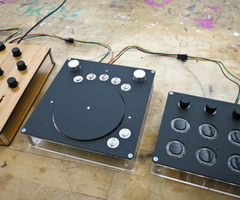
MIDI controllers are used to control music software. They can be as simple as little-scale's wireless MIDI knob or as complicated as Fuzzy Wobble's controllers. The MIDI controller you'll have at the end of this tutorial will be on the simple side, but hopefully it will give you enough information to start building something amazing. Start with the software. You will need the Arduino IDE (get an earlier version) and the Teensyduino add-on. Follow the directions linked below.
|
|

|
step 1: microcontroller
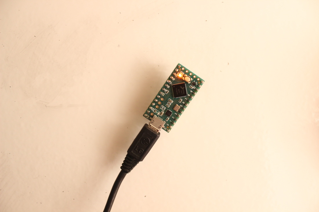
The microcontroller is the heart and soul of this MIDI controller. It is the brain that will read inputs and talk to the computer, sending and receiving MIDI information.
We will use a prototyping setup later in the tutorial, but for now you can just use the board by iteself. |
step 2: blink
|
Now, get the code. The 'blink' sketch is one of the standard sketches that people use to make sure the Teensy is working correctly and that all of the software is set up correctly. It tells the Teensy to blink its on-board LED for one second, every second. Conveniently, the Arduino IDE comes with 'blink' prepackaged and ready to go. Open Arduino, and go to File > Examples > 01.Basics > Blink.
Read the comments (gray text following '//' or between '/*' and '*/') to figure out how the code works. If you're using a Teensy 3.1 or a Teensy LC, the code is ready to go. The code is copied below. Go to Tools > Board and select the Teensy module that you have. Then, go to Tools > Port and select MIDI USB. Then click verify, and upload. |
|
/*
  Blink
  Turns on an LED on for one second, then off for one second, repeatedly.

  Most Arduinos have an on-board LED you can control. On the Uno and
  Leonardo, it is attached to digital pin 13. If you're unsure what
  pin the on-board LED is connected to on your Arduino model, check
  the documentation at http://arduino.cc

  This example code is in the public domain.

  modified 8 May 2014
  by Scott Fitzgerald
 */


// the setup function runs once when you press reset or power the board
void setup() {
  // initialize digital pin 13 as an output.
  pinMode(13, OUTPUT);
}

// the loop function runs over and over again forever
void loop() {
  digitalWrite(13, HIGH);   // turn the LED on (HIGH is the voltage level)
  delay(1000);              // wait for a second
  digitalWrite(13, LOW);    // turn the LED off by making the voltage LOW
  delay(1000);              // wait for a second
}
If prompted, press the 'reset' button on your Teensy. If it isn't the Teensy's first use, just click upload. The orange LED on the board should blink. Success! You have created life. Bask in the orange light of your success.
step 3: midi blink
You can see where the code is telling the LED to turn on:
void loop() {
  digitalWrite(13, HIGH);   // turn the LED on (HIGH is the voltage level)
  delay(1000);              // wait for a second
  digitalWrite(13, LOW);    // turn the LED off by making the voltage LOW
  delay(1000);              // wait for a second
}
You can probably guess what we'll do from here- instead of turning on the LED, we want the Teensy to send MIDI information to the computer. All sketches are made up of at least two parts - a setup and a loop. The setup runs once when the Teensy receives power. The loop runs forever, over and over again at a really fast pace after the initial setup. To make the controller send MIDI while blinking, we have to make a small change to the loop section of the code. First, find where the code turns the light on:
digitalWrite(13, HIGH); // turn the LED on (HIGH is the voltage level)
Add this line of code below it. It turns on a MIDI note; C4 to be exact. The 60 represents the pitch, the 100 represents the velocity, and the 1 represents the channel. You can change these values and the code will still work the same.
usbMIDI.sendNoteOn(60, 100, 1); // send a MIDI note on channel 1
Now find where the code is telling the LED to turn off . . .
digitalWrite(13, LOW); // turn the LED off by making the voltage LOW
. . . and add command to turn the note off. Make sure to use the same pitch and channel number you used before.
usbMIDI.sendNoteOff(60, 100, 1); // turn the MIDI note off
test!
step 5: button code
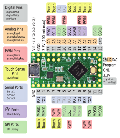
Now, let's add some input components. The pins around the perimeter of the Teensy allow it to connect to external components and read their status. Using these components, we can interact with the code and use the Teensy as a bonafide MIDI instrument. First, we need to go over some new coding concepts. First, look at the section of the code above the setup area.
int led = 13;
|
You can see here that when "led" appears in the code, it is a substitute for the number 13—the pin connected to the Teensy's LED. In simple sketches, it is easy to just use numbers. As the code gets more complex, however, words help keep things straight.
We are going to connect a button, so we need to decide which pin to use and declare it. I am using pin 0, so I wrote this: int led = 13; int buttonPin = 0;
The name can be whatever you want, and you can use any pin in the chart above (except Vin, 3.3V, or GND).
Now you need to add something to the setup. I deleted the comments so it's easier to read. You can keep them if you want, or add your own more helpful ones. Here's what we have: |
|
void setup() {
  pinMode(led, OUTPUT);
}
And here's what we need:
void setup() {
  pinMode(led, OUTPUT);
  pinMode(buttonPin, INPUT_PULLUP);
}
The "pinMode" command is used to set up pins for what they need to do. The first one sets up the LED on pin 13. The second one is going to allow us to use a button on pin 0.
Now we can add the button code to the loop. I want the "MIDI Blink" loop to run when the button is pressed. This is what I use to make that happen:
Now we can add the button code to the loop. I want the "MIDI Blink" loop to run when the button is pressed. This is what I use to make that happen:
int led = 13;
int buttonPin = 0;
// the setup routine runs once when you press reset:
void setup() {
  pinMode(led, OUTPUT);
  pinMode(buttonPin, INPUT_PULLUP);
}

// the loop routine runs over and over again forever:
void loop() {
  if(digitalRead(buttonPin) == LOW) { //if the reading on pin 0
                                      //indicates that the button is pressed...

    digitalWrite(led, HIGH);
    usbMIDI.sendNoteOn(60, 100, 1);
    delay(1000);               // wait for a second
    digitalWrite(led, LOW);
    usbMIDI.sendNoteOff(60, 100, 1);
    delay(1000);               // wait for a second
  }
}
|
step 6: button setup
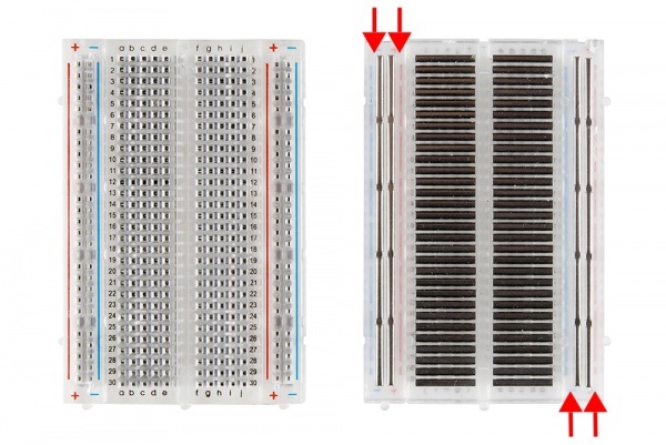
A quick note about breadboards. Breadboards are little platforms on which you build circuits to try them out. All you do is stick the component leads into the little holes, and the breadboard links them without soldering or making any permanent connections. The long, vertical rows in this picture are called the rails—they form connections in a horizontal line, and usually carry the power and ground voltages. The holes in the middle are connected in horizontal lines. Photo credit to Sparkfun.
step 6.1: power and ground
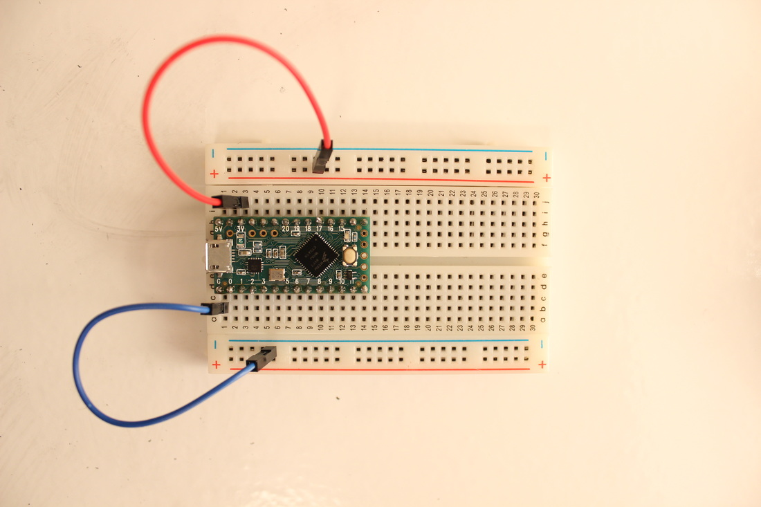
The first thing we have to do is put the Teensy into the board. Then, we need to connect the 3.3V (power) pin to the power rail (usually red) and the GND pin to the ground rail (usually blue or black). Use the picture for reference. The pinout diagram above may also be helpful.
step 6.2: hook up the button
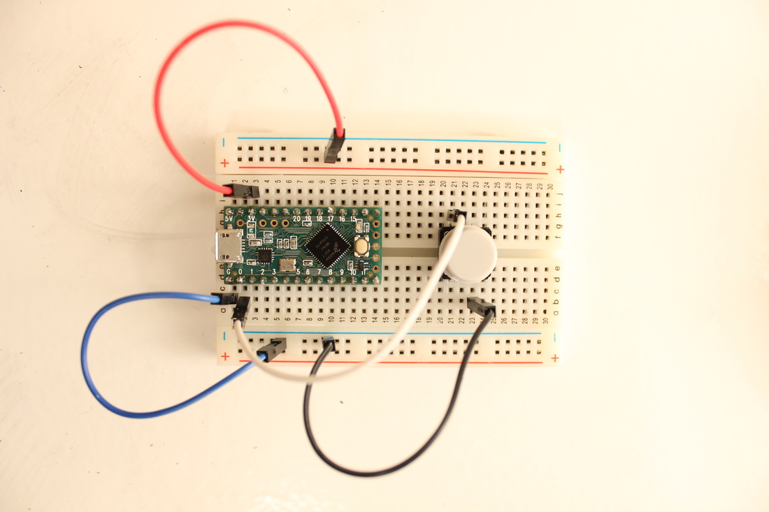
Then, hook up the button. The "buttonPin" (pin 0 for me) connects to one of the pins on the button, and the pin opposite and diagonally from that one connects to ground as shown. This sets up the pin as a normally off, on if pressed switch.
step 6.3: upload and test
Does it work??
|
step 7: control change
|
We have been dealing exclusively with on-off signals so far. But as you may already know, there is another important flavor of MIDI information: control change. CC MIDI information is continuous instead of on-off, meaning that you can use it to control things like volume, filter cutoff, compression ratio, etc. To achieve this, we use analog components to generate a signal that ranges from 0 to 1025. Then, we use math to map that number to a value between 0 and 127. Finally, we send the MIDI. Here is the code that I use for that. Pay attention to how the variable declaration, the setup, and the loop change.
|
|
int led = 13;
int buttonPin = 0;
int analogPrev;
int knobPin = A0; //this is an analog pin. Consult the pinout for a complete list

void setup() {
  pinMode(led, OUTPUT);
  pinMode(buttonPin, INPUT_PULLUP);
}


void loop() {
  if(digitalRead(buttonPin) == LOW) { //if the reading on pin 0
                                      //indicates that the button is pressed...

    digitalWrite(led, HIGH);
    usbMIDI.sendNoteOn(60, 100, 1);
    delay(1000);               // wait for a second
    digitalWrite(led, LOW);
    usbMIDI.sendNoteOff(60, 100, 1);
    delay(1000);               // wait for a second
  }
  int analogReader = analogRead(knobPin); //analogReader is a temporary variable

  if(abs(analogReader-analogPrev) > 20) { //if the value on the knob > 20 different than before
    int midiSend = map(analogReader, 0, 1023, 0, 127); //map the values
    analogPrev = analogReader; //store the value for later
    usbMIDI.sendControlChange(1, midiSend, 1); //send MIDI
  }
}
|
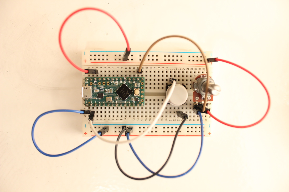
step 8: pot' setup
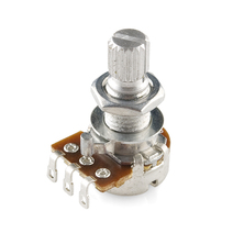
Potentiometers are kinds of variable resistors. You may know them as knobs, faders, or pots. We use them to read analog information (continuous variables). The middle pin is the one we read, so hook that one up to the Teensy at the pin you declared in your sketch. The other two go to each rail (it doesn't matter which one goes to which, just don't connect them or the pot will start to smoke). Once it's hooked up, upload the code and test!
|
 RSS Feed
