BUILD A SYNTH
by Jon M. Stapleton
| Synthesizers are made up of lots of parts—oscillators, effect modules, filters, sequencers are some common ones. This tutorial is intended to help you learn about the most basic element of synthesis: oscillation. Oscillators are very easy to build, and are incredibly flexible. You can do a lot with only a few components! This tutorial is based on this one from the Electronoize Playshop. | 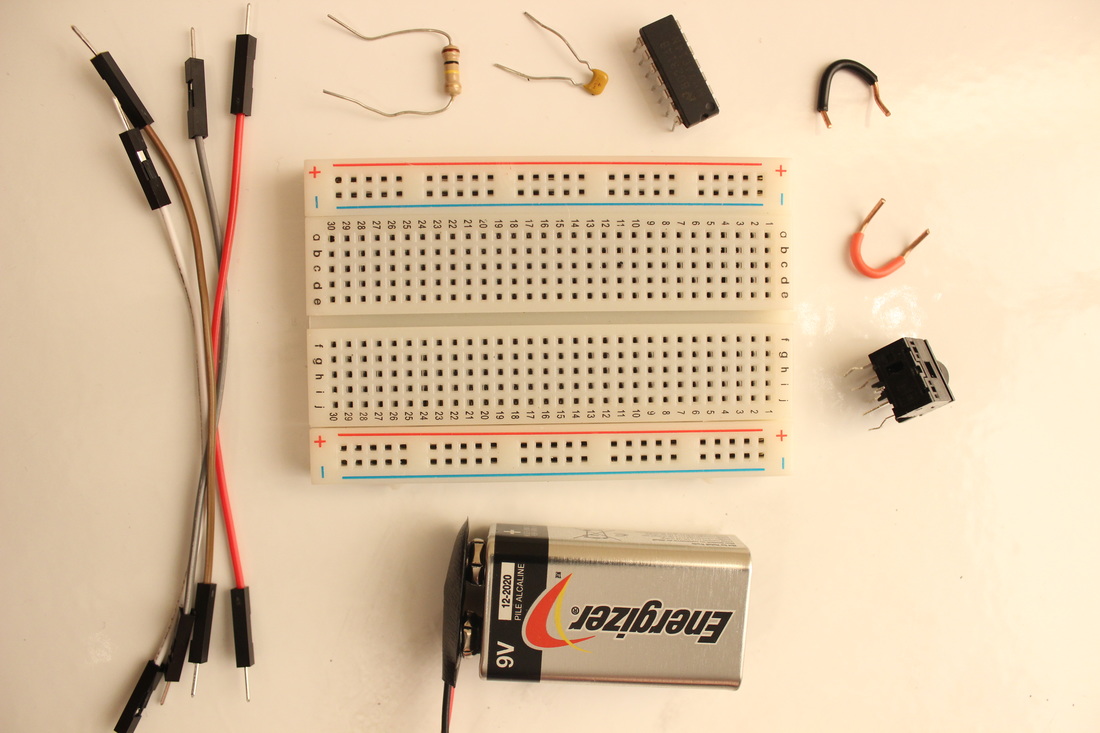 |
step 1: how to breadboard
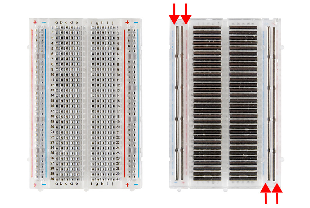 | If you already know how a breadboard works, go ahead and skip to step 2. If you don't, worry not. Breadboards are little platforms on which you build circuits to try them out. All you do is stick the component leads into the little holes, and the breadboard links them without soldering or making any permanent connections. The long, vertical rows in this picture are called the rails—they form connections in a horizontal line, and usually carry the power and ground voltages. The holes in the middle are connected in horizontal lines. Photo credit to Sparkfun. |
step 2: hook up the ICThis is the easy part! the CD40106 IC (integrated circuit) will straddle the line in the middle of the breadboard, like in the picture to the right. Make sure that the indentation is going to the left. Then, connect pin 14 (top left) to the +9V rail and pin 7 (bottom right) to the -9V rail as shown. | 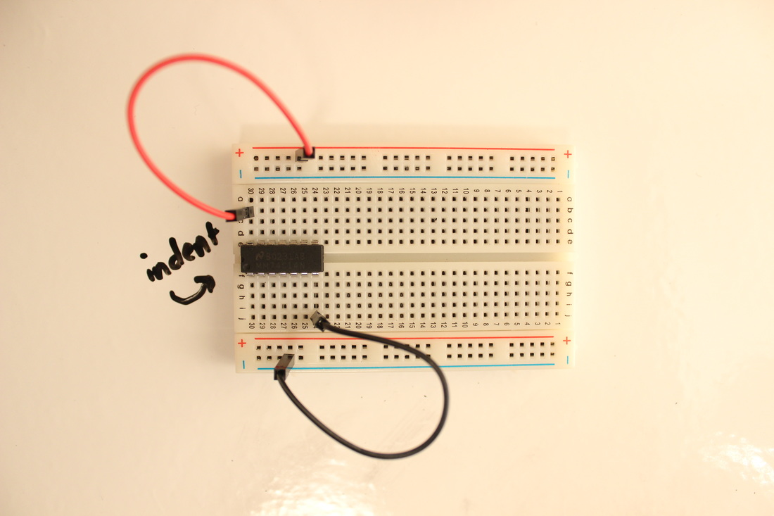 |
| Here is a diagram with the pins of the CD40106 labeled. The symbols on the inside represent Schmidt triggers, which are little circuits which allow us to create oscillators. I'll go into more detail at the end of this tutorial. Photo credit to the Electronoize Playshop. | 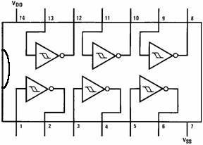 |
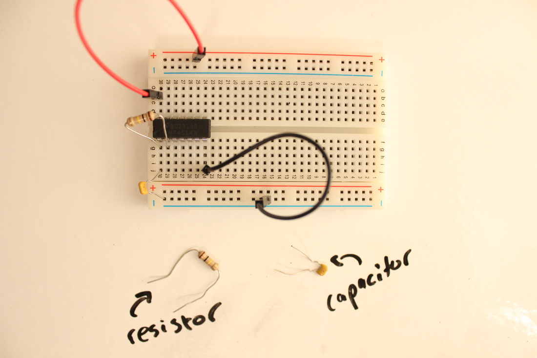 | step 3: componentsNow, you'll add a capacitor and a resistor. I used pins 1 and 2, but there are spots for oscillators on every pair of pins (1 & 2, 3 & 4, 5 & 6, etc.) with the exception of the positive and negative voltage pins, of course. Add the capacitor and resistor as shown, with the capacitor between pin 1 and -9V and the resistor between pins 1 and 2. |
step 4: oscillate!
| Time to see if it works! Put the headphone jack on the breadboard as shown and connect it to speakers or headphones. Once everything is hooked up, make sure the volume on the speakers is turned down all the way and connect the battery to the power rails—red to the +9V side, and black to the -9V side. Turn up the volume; if you hear a beep, you have succeeded! If not, check to see if anything (including the battery) is getting hot. If so, rip that battery out of the circuit and check for direct connections between +9V and -9V. If nothing is hot and it still isn't working, double check the breadboard connections. It is pretty easy to accidentally connect the wrong things. | 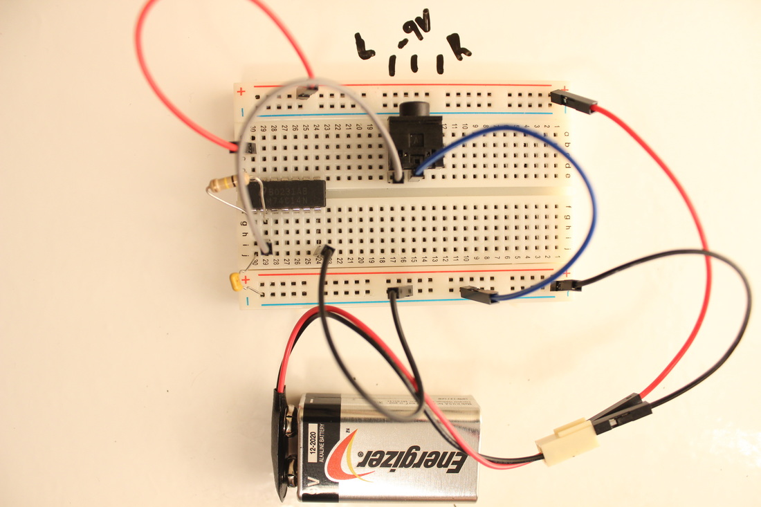 |
step 5: experiment
crude mixer:Set up another oscillator on a different pair of pins. Use resistors to send the output of each oscillator to the same vertical row on the breadboard. The resistors help make sure the mixed signals don't get out of hand. Send the mixed signal to the headphones. 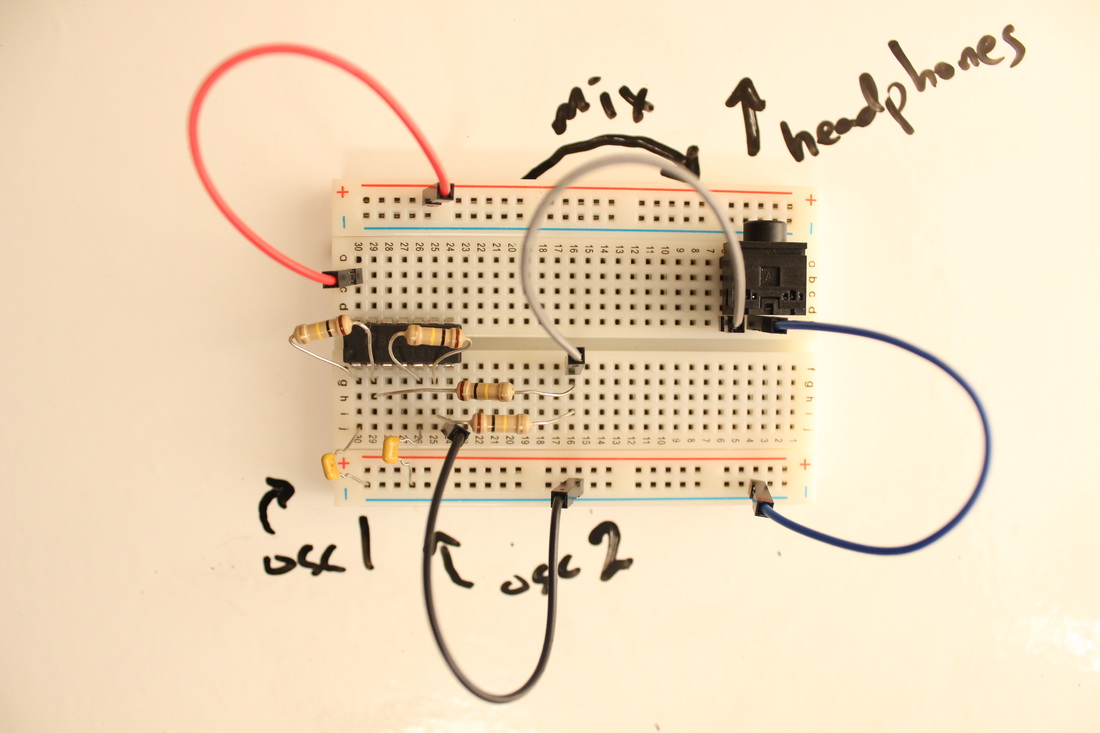 potentiometers:Potentiometers (pots for short) are variable resistors. This means that they can be used in place of a resistor, but they can be different levels of resistance based on the position of the knob or slider. This picture shows you how to hook it up. Try using pots in different places in the circuit to see what kind of effect it has on the sound. | frequency modulation:Set up two oscillators. Send the output of one (in this example, pin 2) to the input of the next (in this example, pin 5) with a diode. Diodes only let electrons flow in one direction. For optimal diode usage, orient the black stripe toward the input signal (the left in this example). 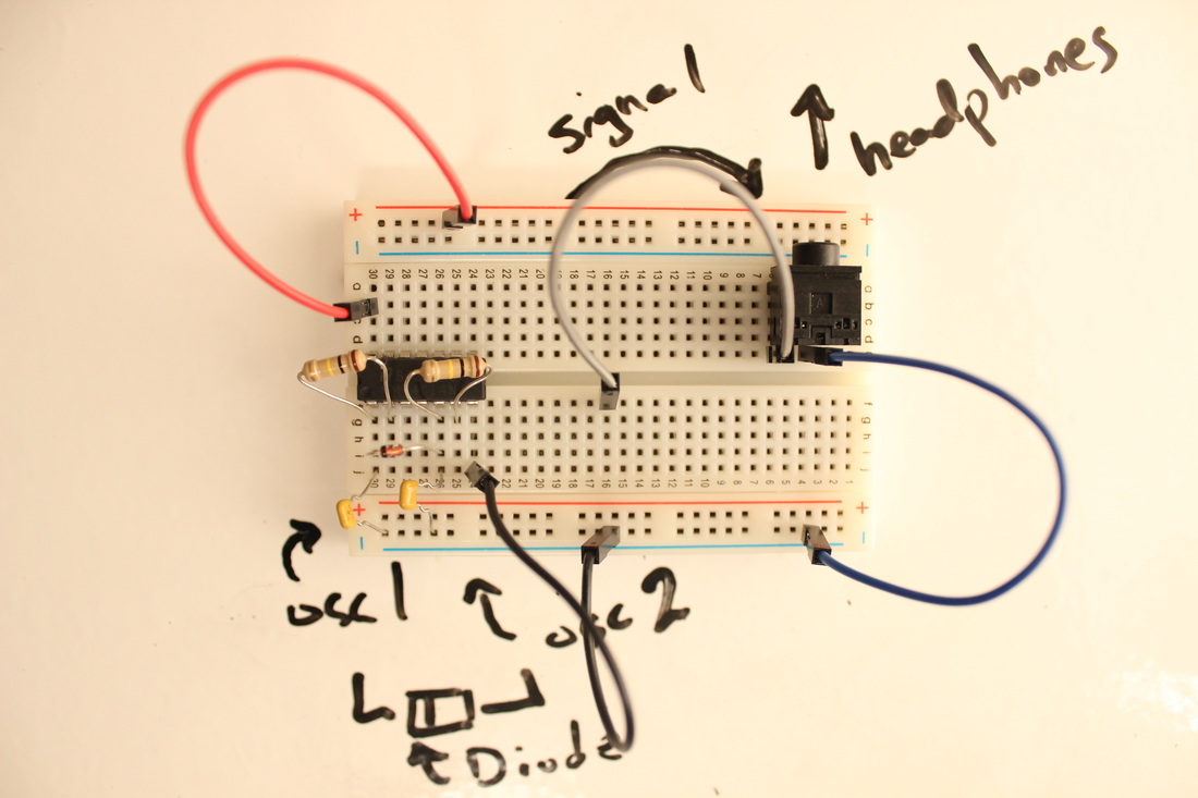 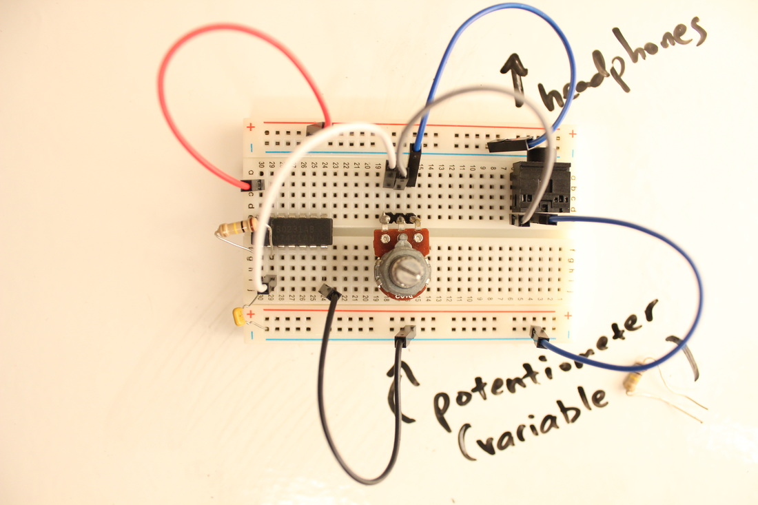 |
more tutorials:
| If you want another thing to do, check out this guy's videos. He also works with the CD40106 and shows off some fun ways of interacting with the circuit. The first video is another explanation of what we just did, with some fun ways of messing with resistance. The second video explains how to make a simple sequencer. His website is also fun. |
| | |
how it works:
| The CD40106 IC is the heart of your oscillator. IC stands for Integrated Circuit, which means that it's a complete circuit in a tiny package. The CD40106 has several Schmidt triggers in it. Schmidt triggers have two elements; when power is applied to the circuit, the two elements will always have inverse voltages. If you connect one side to the "high" voltage, the other side will read "low." (Photo credit: Electronoise Playshop) |  |
The simple circuit you built feeds the output of the Schmidt trigger back into the input, causing the voltage on the pins to switch back and forth rapidly. The resistor and capacitor slow down that process. The capacitor fills up with voltage; when it reaches a certain point, the electrons empty into the pin which reads low, causing it to read high and for the other pin to read low. The electrons will then flow back into the capacitor until it causes the pins to switch again. This oscillation (see where I'm going with this?) makes a sound if it's fast enough. The size of the capacitor and resistor affect the pitch; the bigger the capacitor, the longer it takes to fill up and the slower the oscillation (lower pitch). The bigger the resistor, the slower the electrons move from one pin to another (lower pitch).
 RSS Feed
